Camshaft Tech: Flat Tappet vs. Roller
Thanks to our new freinds at T and L Engine Development, Inc for this How-To article. Stay tuned for an article and build info on their 575 HP all aluminum Ford Small block 427! Also, be sure to check out their Ebay Store for the best in Ford and Chevy engines.
Upgrading to a roller camshaft; is it cost efficient?
Pictures and text by Eric LaBore
Camshafts have always been and continue to be the basis of argument among many engine builders and car enthusiasts alike. How much lift, the right duration, lobe centerlines and separation angles, there are so many aspects and conditions to consider. It requires many years of research, experience and an in depth understanding of the internal combustion engine to become an expert in choosing the best possible design. However, one thing that is widely agreed upon; for the best performance and reliability, a roller camshaft is the way to go.
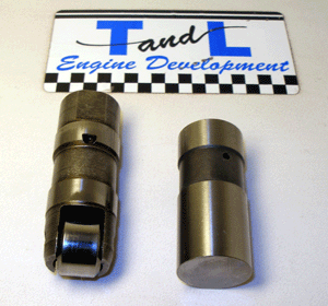
There are two basic categories among camshafts; flat tappet and roller. Flat tappet cams are the ones most people are familiar with. Most of your V-8 engines in the muscle car era came standard with a flat tappet cam. The tappet, more commonly referred to as the lifter, is, for the most part, flat on the bottom. Oil film is the only thing between the lifter and camshaft lobe preventing them from welding each other together. Eventually, the cam lobes would wear down to a circular shape rather than the teardrop shape they started as. This, in turn, would not open the valves far enough to completely fill the cylinders with a fresh charge of air and fuel or allow the used charge to fully exit through the exhaust. A major loss in power and efficiency was the result. Fortunately, the roller cam almost completely eliminates this wear factor. Roller camshaft lifters are equipped with an actual roller that rides on the cam lobe. (Figure 1) This obviously results in a much longer lobe life due to the reduced friction.
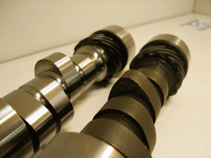
Fig. 2 Comparing Cam Lobes – The roller camshaft (on the left) has steeper opening and closing ramps which allows for more time at max lift.
In addition to the reliability factor, roller cams also have a great performance advantage over the flat tappet. The faster you can get the intake valve to maximum lift, the longer it can stay there before the piston comes rushing back up the cylinder to compress the air fuel mixture. If the goal is to load the cylinder with as much air and fuel as possible, the longer you are at maximum lift the better. Flat tappets require a smoother transition from the base circle of the cam to max lift, leaving less time for the lifter to dwell there. Roller lifters, on the other hand, can survive a much more abrupt transition resulting in extra time at max lift. If you compare a roller cam lobe to a flat tappet lobe, you can see the roller cam has a larger radius at its peak, holding the lifter at max lift for a longer duration. (Figure 2)
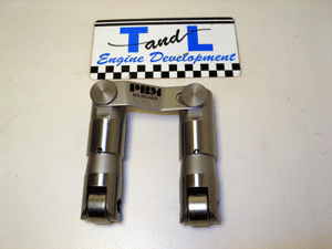
With all that said, I think you would agree that a roller cam is the better choice from a reliability and performance standpoint. Now let’s look at some of the things required with the use of a roller cam. To keep lifters on a flat tappet cam wearing evenly, they are designed to rotate in the lifter bore with each revolution of the cam lobe. Not only is this not required on a roller lifter, it is definitely not desirable since rollers only work in one direction. There are two ways to eliminate the rotation of a roller lifter in its bore. On newer blocks that came standard with a roller cam, the top of the lifter bores are machined flat. The upper body of the lifters used with this type of block is also machined flat on two sides. This allows for the use of a special retainer, often referred to as a dog bone, which prevents lifter rotation. (Figure 3)
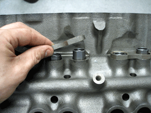
Fig. 3 Eliminating Lifter Rotation – Retainers are used to prevent the roller lifter from rotating in its bore.
If an older version block or a solid roller cam (often used in higher RPM and racing applications) is being used, tie bar lifters are required. In this design, the intake and exhaust lifters are connected by a flat bar preventing any rotation. (Figure 4)
To prevent cam walk, flat tappet cam lobes are slightly tapered, keeping the camshaft centered under the lifter bores. Since rollers must have a flat surface to roll on, roller cams require another way to keep the cam centered. Some blocks accept a retainer plate that bolts to the block behind the cam gear. Only a roller cam that is machined to accept this retainer can be used. (Figure 5)
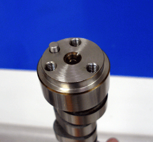
Fig. 5 Machined for Retainer Plate – Notice the front of the cam is stepped to accept a cam retainer plate.
If the block or camshaft does not accept this retainer, a thrust button must be used. Thrust buttons fit between the front of the camshaft and the timing cover, preventing the cam from walking forward. (Figure 6)
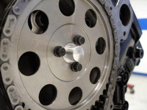
Fig. 6 Thrust Button – A thrust button is installed between the cam gear and the front cover to control forward movement of the camshaft.
Rearward movement, in all cases, is controlled by the cam gear.
One last thing must be upgraded with the use of a roller cam. Since the opening and closing ramps of the cam lobes are usually more aggressive, a higher rate valve spring must be used. If not, the lifter could actually lose contact with the cam lobe at high RPM. The stronger spring will also prevent the valve from bouncing off its seat when it is slammed shut.
Now that you have a general idea of the differences between a flat tappet and roller camshaft, let’s answer the original question. Is upgrading to a roller camshaft cost efficient? First of all, the reliability factor by itself is almost enough to justify a few hundred extra dollars. Then add in the twenty to forty extra horsepower; I would say yes, its money well spent.




“compare a roller cam lobe to a flat tappet lobe, you can see the roller cam has a larger radius at its peak, holding the lifter at max lift for a longer duration”
Complete nonsense.
Perhaps you might try some BOCES courses on geometry?
Thanks for the comment Panic, however, isn’t it kinda shitty to say that it’s “Complete nonsense” then you don’t enlighten us with the facts?
Maybe you’re still finishing your geometry course?
I’ll stand by what T&L says and assume this is some kind of misunderstanding…
A flat tappet cam can be formed to have a max lift similar to a roller cam; however, because of the rollers, the slope of the lobes on a roller cam may be steeper then the slope of the lobes on a flat tappet cam. The steeper slope the slope of the lobe, the faster the change in valve position. The faster rate provides the opportunity to create cam profiles that are almost unachievable, and less reliable, with a flat tappet cam.
In fig 2, a flat tappet and roller cam are compared. From this diagram, one can see a significant difference in the profiles of the two cams. The roller cam has a slope that is almost vertical, while the flat tappet is very egg shaped.
Of course, all cams cannot be generalized from one example. However, comparing the most extreme (and functional) profiles, the roller cam is typically steeper. It does come down to geometry, but the concepts seen here are based in physics…
“assume this is some kind of misunderstanding”
Yes, I see you still don’t understand it.
Don’t read too much into this. The duration is significant as well as max lift. The roller cam may or may not have a larger radius than the flat tappet cam when the radius is at its max length (it all depends on the particular grind). The idea here is that the roller cam has potential for longer duration. Just before and after max lift, the lobes on a roller cam may have a larger radius then the lobes on a flat tappet.
Roller cams are far superior because they increase angle (steepness) the closing and opening ramps that have to be ground into a flat tappet cam to prevent lifter’s from jamming up in the first place. Roller lifters can take a steep ramp because of their wheel design. Once a valve reaches 0.300″ of lift (valve lift, not cam lift) it is less restrictive to air flow. So the intent is to get the valve to max list ASAP so that it can be less restrictive. This increase air flow, which in turn increases power and economy. VVT systems take advantage of what we learned by using roller cams. A roller cam’s duration is measured at the same points as a flat tappet cam. SAE standards start duration measurement at 0.006″ of lift. Whereas racing cams often start the duration measurement at 0.050″ of lift. If you compare the two cams in the picture above they have approximately the same duration. Duration is technically defined as the amount of time the valve is open (just time, not airflow, lift, etc.).
So the roller cam does have a different radius near the top of the lobe, but that is only because of the opening and closing ramps being steeper and taking advantage of the lower friction of the roller lifter.
I guess I’ll add my two cents worth here. From what I can see Eric is completely correct in his explanation of the differences and benefits of flat tappet vs. roller except for one very crucial fact. Since the EPA has now mandated the removal of zinc and phosphorous from most passenger car and truck motor oils, there is one more comparison that needs to be addressed. Will a flat tappet cam even survive the break-in period let alone it’s intended use be that street or racing use? Even the major cam companies will tell you that it is nearly impossible to make a flat tappet cam survive the break-in period, even using all the correct additives and procedures. Due to this fact alone the roller cam wins hands down! If it was as simple as just taking the failed cam and lifters out and replacing them (and attempting another break-in) that might not be too bad, but it gets much more expensive than that. All that metal has now been pumped through the entire engine destroying the oil pump, bearings, and sometimes even the crank and piston skirts. So now that “few extra hundred dollars” isn’t looking so bad is it? I will no longer build an engine in my shop using a flat tappet cam unless the customer signs a waiver stating he realizes the risk of doing so.
Brian Cunningham
Crossroads Speed Equipment
roller cam is better hands down regardless
So the power increase comes from the valves being at high lift for a longer part of the cam rotation, and from opening faster and from the reduction in friction. Has anybody measured the reduction in friction in units of horsepower? As if you put in rollers and used a camshaft with the same profile? Thanks
Tom: You’re right, but maybe it’s easier to think of it in terms of air. Engines are air pumps. The more air they can move, the more power. More air comes from valves that are open for longer. That more air gets combined with more fuel and that makes more power. I think friction of a roller vs. flat isn’t a measurable amount in terms of horsepower.
Love the article, clears up what I should have already known.
I appreciate the comments too, with the exception of this panic character.
wish I had info to add but, still learning.
Interesting subject perhaps I can add something. The roller cam duration looks like it would be longer right, not really. Think of it this way – The roller cam time at max lift is almost entirely a function of the cam due to the extremely small contact area of the roller. While the flat cam time at max lift is controlled by the top of the cam within limits and the rest of the duration at top is controlled by the diameter of the lifter. The top of the flat cam has to wipe the entire diameter of the lifter before it starts down. The contact diameter of the flat lifter also affects, among other things, when the lifter starts to rise.
No doubt about it though, the roller setup is by far superior if for no other reason than the huge reduction in friction.
A few of you are looking at this from a complicated point of view. Laymans terms: we’re not talkling about max lift. Max lift is only achieved for a split second at the very top of the lobe. We’re talking about NEAR max lift and its duration. The roller is able to get us there much faster. Think of it like two people trying to slide wooden boxes up a hill. One has a dolly, and one is slidding his on asphalt. Which one makes it there first and who can go up a steeper hill? Because the roller makes it there much faster, and the time that the valve stays open is proportional to RPM (basically proportionally constant), the roller cam is able to keep the a larger opening longer, allowing more air and fuel into the cylinder. Technically, both cams keep the valve open the same amount of time if you look at it as it’s open unless the valve is seated. But in terms of horsepower, we don’t look at it that way. We want that opening as big as possible for as long as possible.
I just read this article from an expert on ZR-1 Corvette engines, which are flat tappet. He calls for a special oil to help prolong cam life…AMSOIL AMO. It’s a short read. Give it a look if you want.
OK, I want to know the same thing Tom asked last year.
I’m not going to drag boxes up a hill (being not the worst analogy I’ve heard) but I think this is a simple question:
IF…. I had an imaginary Roller Cam that produced the exact same Lift / Duration profile as my imaginary Flat Tappet Cam, (say around 0.450 to 0.500 lifts just so you know I don’t mean extreme), THEN……………
Can JUST the reduction in friction add more than say 5 Hp? or inversely stated , Free up 5 or more Hp lost to friction and heat from a flat tappet?
I want to get all the power I can from efficiency first BEFORE I burn more fuel to do the same thing.
Thanks, Anyone…
I think I found my answer here at Comp Cams:
http://www.compcams.com/technical/FAQ/FAQLifters.asp
… ” reduced valve train friction (often a 15+ hp increase) ” ….
Is this a true statement?
If it could be done without the cam walk issue or wear issues, replacing flat lifters with roller lifters without changing to a roller cam would result in a decrease in performance due to the small contact point of the roller on the lobe compared to the flat lifter contact on the lobe.
I realise this is an old thread but in case anyone is using it for research it should be pointed out that what Panic said at the beginning is in fact true (but not very helpful). The shape of the cam lobes for a roller cam look different because of the way the contact patch works for a roller follower. Effectively the roller acts as a point conact so the movement of the rod follows the exact shape of the lobe (not quite true but close enough). On a flat lifter the point of the lobe holds the rod up for the whole time it takes to sweep across the face of the follower (again not quite true) – the rod movement does not follow the cam profile but looks much more like the roller version than you would expect. So a mild roller profile looks like an insane flat lifter profile by just looking at the lobes, which was Panic’s point. Saying that, there are some benefits from running a roller cam, especially in frictional savings and reusing them after a cam change.