10-second Check to Avoid 3 Common Valve-lock Troubles in Racing Engines
Valve-Lock Inspection to Save your Engine
By Fergus Ogilvy
Photos by Moore Good Ink
This advice may only help hard core race engine builders, but any time we have a chance to publish high quality tech like this info from Trend Performance, we’ll do it. Wish I would have saw this before putting the valves back into my Falcon! (course that’s anything but a racing engine!) Enjoy!

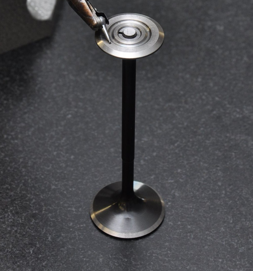
Assemble the valve locks on a valve and using your thumb and forefinger raise the spring retainer to its full height. If the assembly defies gravity and remains in place and doesn’t rock, the quality of the valve locking assembly is superior. If, however, the assembly falls apart, the valve locking mechanism is deficient in one or more of its dimensions.
The three critical dimensions of the valve lock
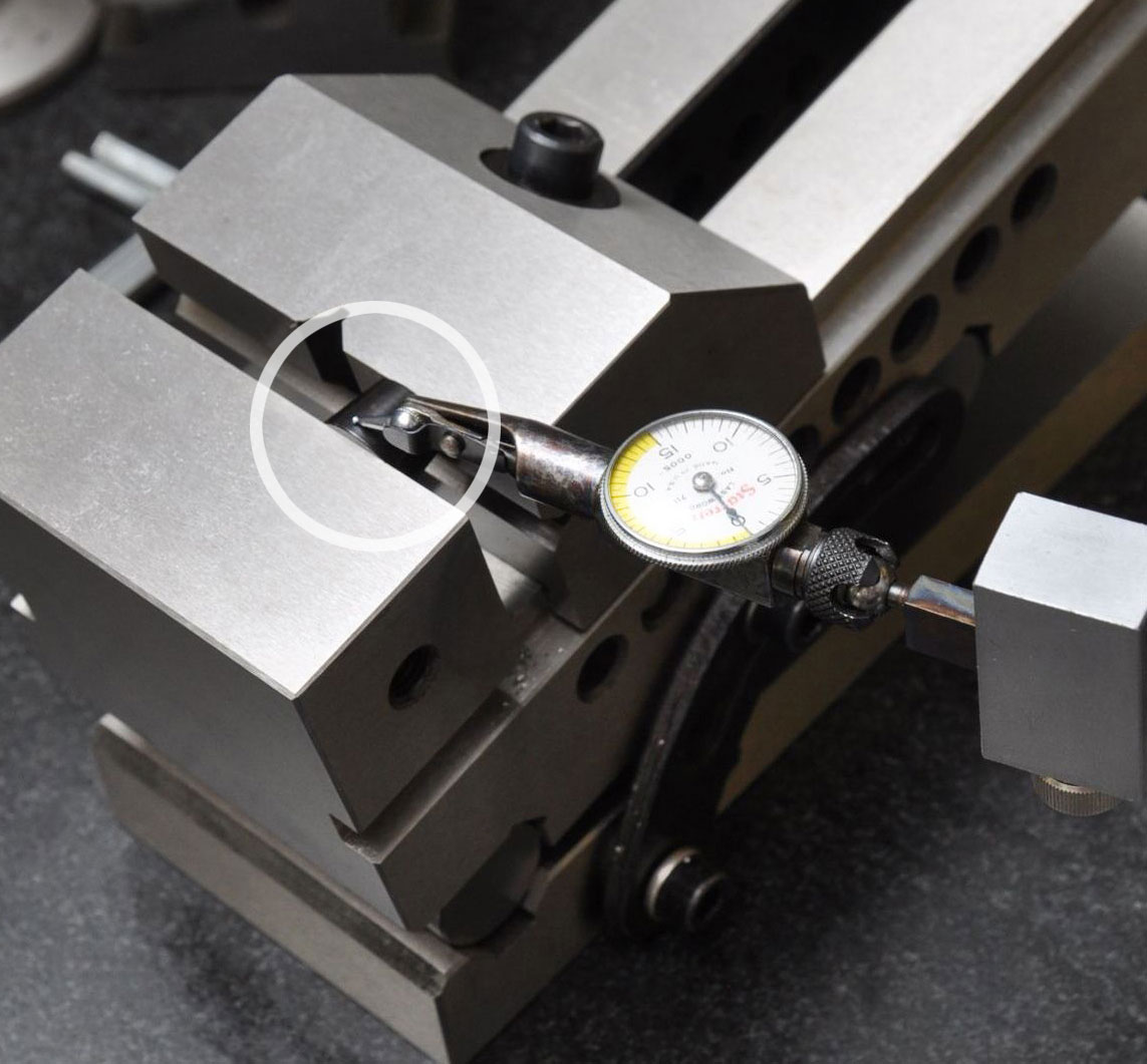
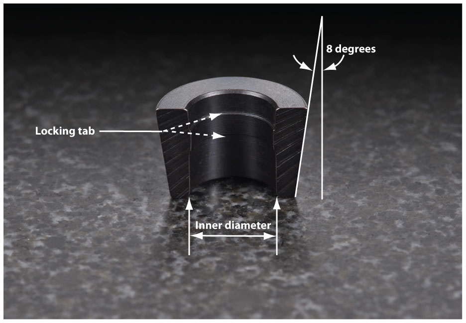
1. The outside angle: The precision of the outside angle, which might be 7, 8, 9, or even 10 degrees, is properly measured on a sine vice. For ease of valve lock removal, high revving racing engines often use locks with the greater angle. The greater the angle, however, the more difficult it is for the parts to accomplish the 10-second check.

To check the outer diameter taper of the valve lock, clamp it in a sine vice, set the vice to the appropriate angle, and confirm the angle is correct with a dial gauge.
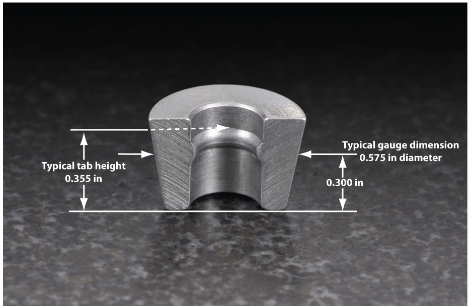
2. The outer diameter: The O.D. of the valve locks is measured at a specific point on the angle. A race engine builder might specify a gauge dimension of, say 0.575in OD at 0.300in high. To check this dimension, simply acquire a 0.575in ring gauge, assemble the locks onto the valve, and measure the position on the angle.

The locking tab fits into the keeper groove. Commonly O.D. tapers vary from 7 to 10-degrees.
Trend machinists check this dimension before they split the locks into two pieces. Any conscientious machinist will have gauge blocks and other checking devices to ensure this and other valve lock dimensions are maintained. Most importantly they reference the gauge dimension with the position of the locking tab in the bore of the valve lock. In race engines this critical relationship must be held to within a few tenths of one-thousand-inch.
3. The inner diameter: The I.D. of the valve lock must fit the valve stem precisely. If the I.D. is too large the locks may have only two points of contact, resulting in a poor connection with the valve stem. On the other hand if it is too small the locks could spread and break. Hardened smaller types are more susceptible to breakage.

The key dimension in all valve locks is the tab location related to the gauge dimension.
As expected, the locking tab fits into the keeper groove. Whether the tab is formed as a radius or with square shoulders, its most important portion is its top region; this is where it interfaces with the keeper groove on the valve stem. Square tabs usually protrude into the keeper groove about 0.011in or 0.012in; radius tabs 0.020in to 0.022in.
Ideally the valve locks should have full engagement with the valve stem, the keeper groove, and the angled interface of the retainer—the fuller the engagement, the stronger the joint. Further, it is preferable that no part of the valve locks should protrude beneath the retainer.
Moreover, valve lock joints are strengthened by the presence of a deeper skirt—a greater clamping area beneath the keeper groove. This directs stresses to the valve stem below the keeper groove. Thus the groove and more importantly the area above it are less threatened.
Thanks for the advice guys! I need to build more engines to try out the tech!
Source
Trend Performance
Brevard, NC
(828) 862-8290
moc.mrofrePdnerTnull@senojC
www.TrendPerform.com


